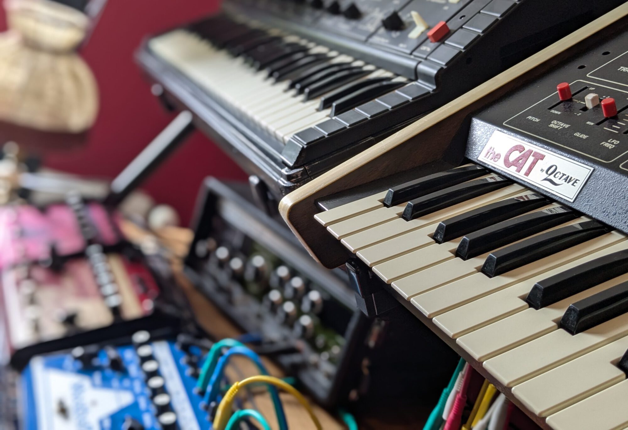

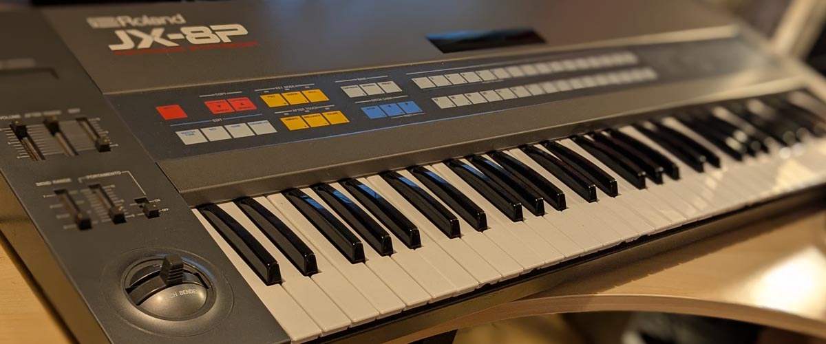
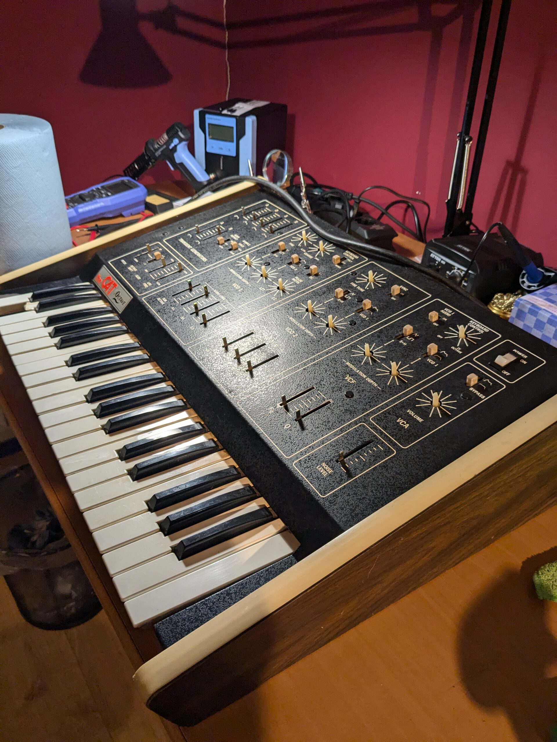
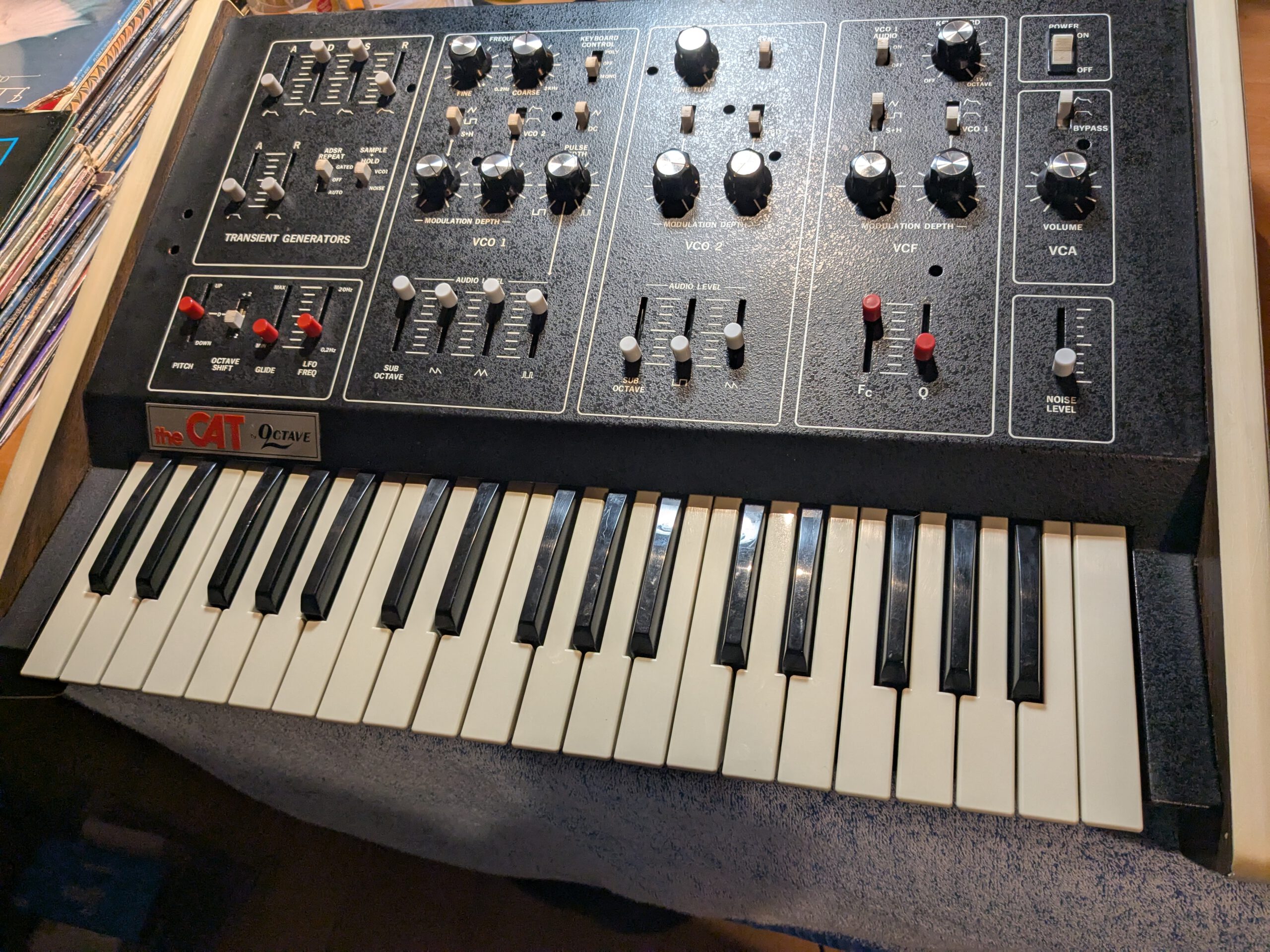
1. A JX-8P with just one issue?
The last two projects went so well. Time to get a bit overconfident. I saw a Roland JX-8P polysynth listed for €250. According to the seller, the only issue was a dead display. Without doing any real research on this particular issue, I decided to buy it. Let’s see if I’m going to regret it.
The synth arrived very well packed, and I powered it up right away to see if it worked. It turned on and produced sound. So far so good. The display was indeed completely dead. I played around with the patches for a minute or so, and then everything suddenly froze. When I turned the JX-8P off and back on, it worked again. I tried to reproduce the issue, and I could. After about a minute, it froze again. If I didn’t touch it for a while, it stayed fine. I started to suspect the power supply.
Another thing I noticed was that the aftertouch seem to work but it needed more force then I was used to in comparison with other synths. I don’t know if I will repair this however as it is playable how it is. I do want to replace five keys which are damaged from the bottom. So that’s something else to look into.
That gave me three issues to start with:
- Dead display
- Freeze issue
- Replace keys
2. Freeze!
I decided to tackle the freeze issue first.
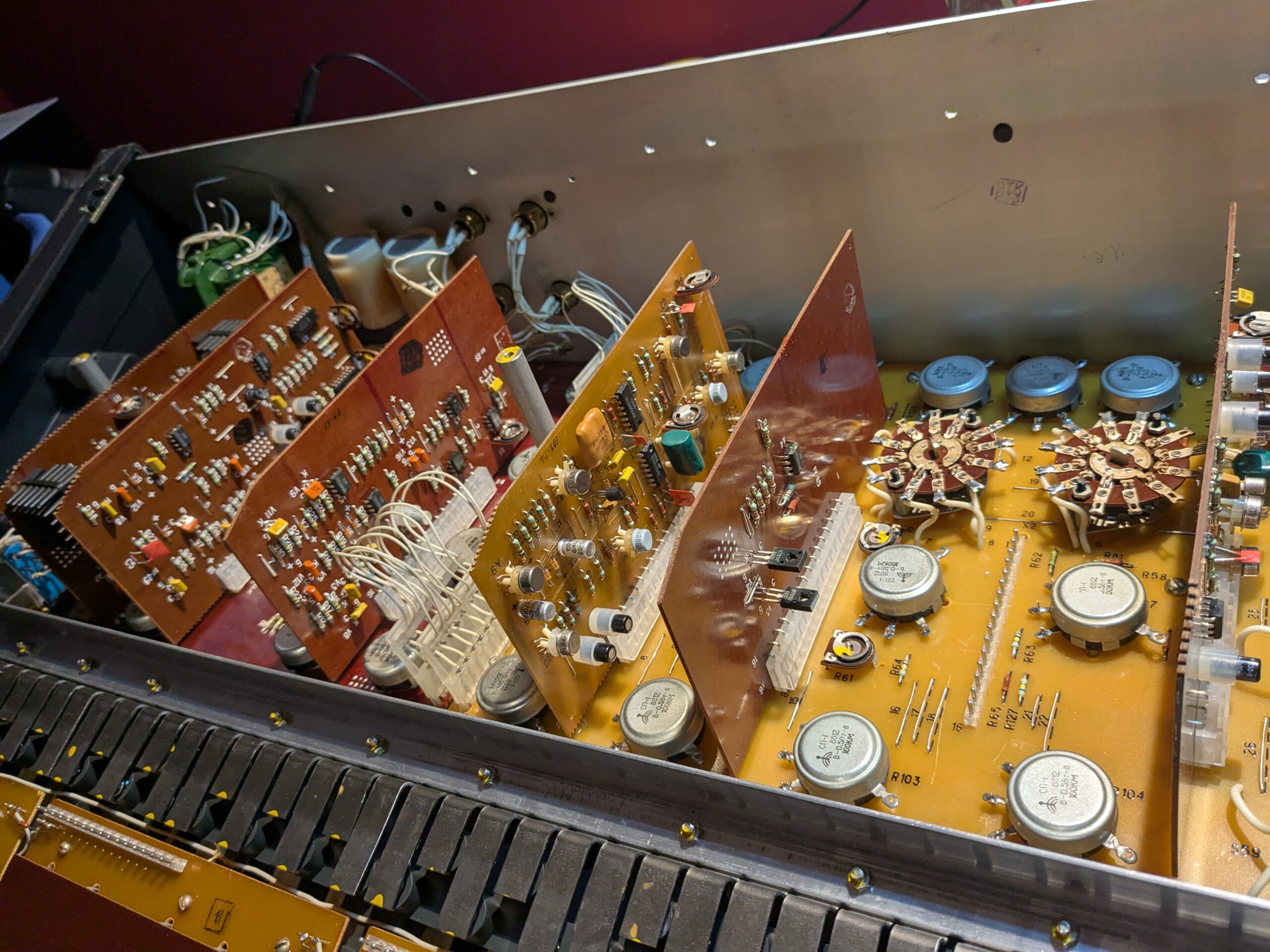
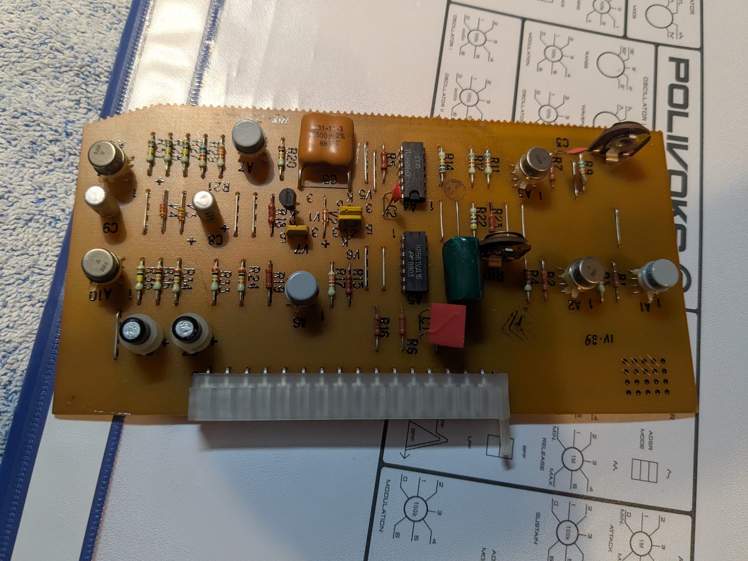
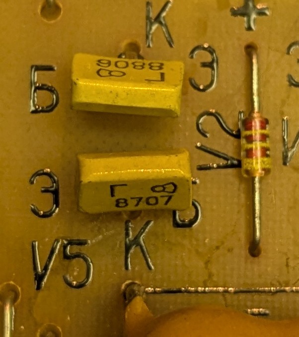
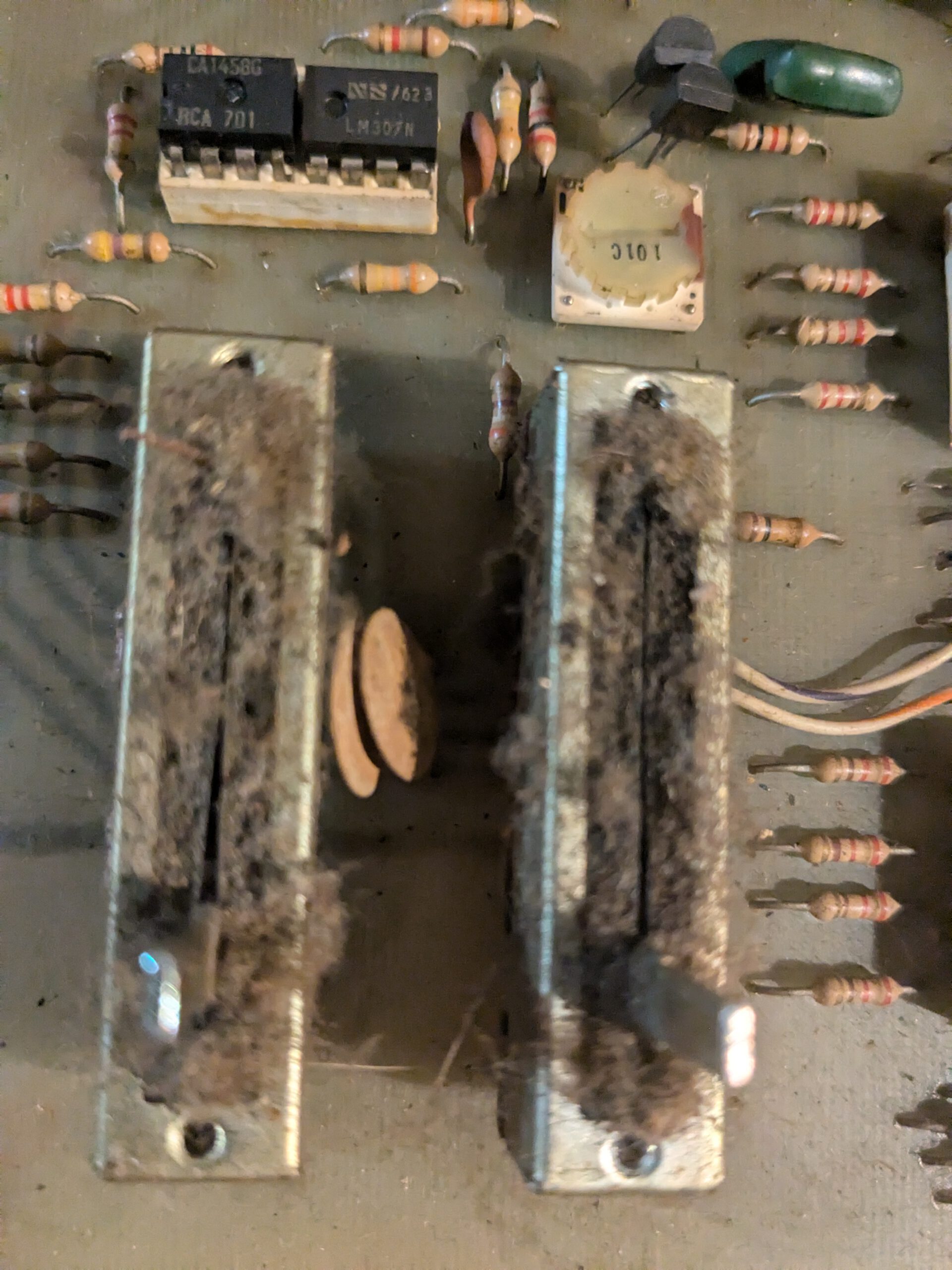
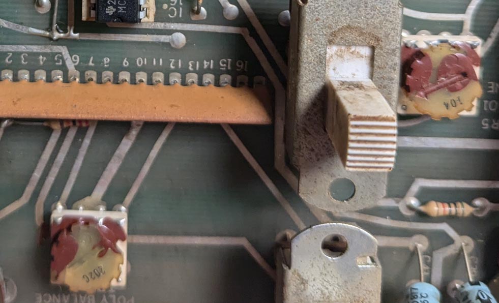
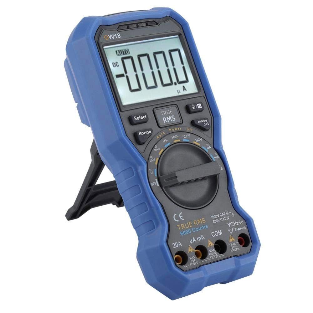
I started by inspecting the power supply and measuring the voltages. I measured 24 volts on the 15-volt rail, which seemed way too high. I noticed the transistors had already been replaced at some point, but it looked like they weren’t proper equivalents. I replaced them with the correct parts: a 2SB507 in place of the 2SB1015, and a 2SD313 in place of the 2SD1406. I also replaced the M5230L regulator IC, since I had read reports of it failing in this synth.
After the replacements, I measured the voltages again. They were a bit lower, but still nowhere near 15 volts.
While inspecting the board more closely, I noticed a burn mark under one of the W02 bridge rectifiers. After reading up on it, I found that it’s best to replace these with higher-amperage versions. I chose a Vishay VS-KBPC602PBF, rated for 6 amps at 200 volts. Unfortunately, they where a bit bigger than expected and the legs didn’t fit through the holes in the PCB. I carefully widened the holes with a 1.5 mm drill bit. They fit now, be it a bit oversized.
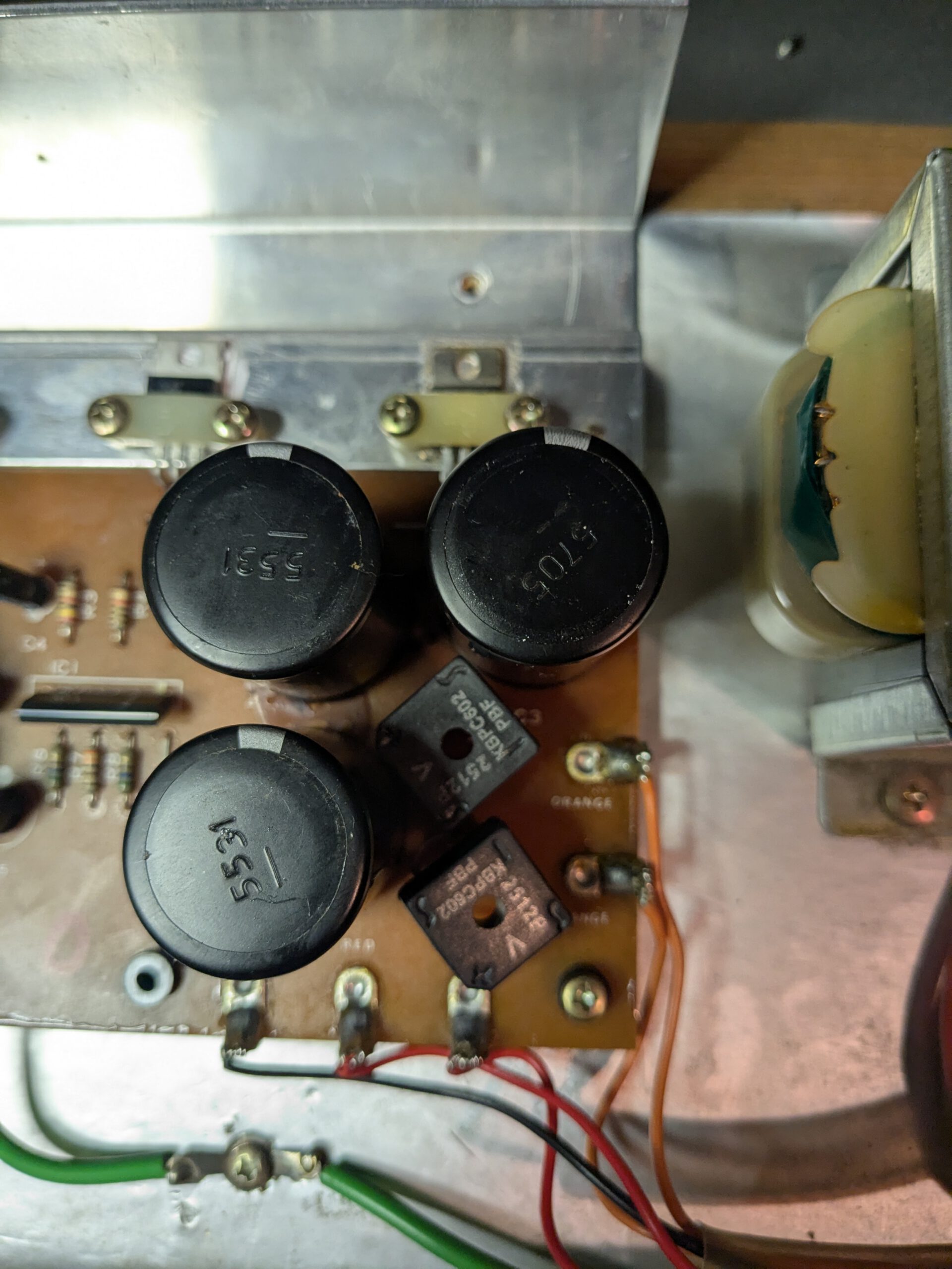
I also decided to measure the ESR of the electrolytic capacitors. They all tested fine, so I left them in place. Removing them had been quite a job , as they were all glued down to the board. I think that was done to prevent vibration. I need to read up on how to remove this glue the easy way.
Time to power it up again. I switched it on, and the fuse immediately blew. What could that be? I figured it must be something with the transistors. I took another look and, aargh, I had forgotten to install the mica insulators between the transistors and the heatsink. That caused a short at the 2SD313. I replaced it again and made sure to install mica insulators on all transistors this time.
I powered it up once more, and it worked. I rechecked the power rails, and now they read exactly 15 volts. Success!
The unregulated 7-volt line, however, was still reading 12 volts. Even after replacing the UA7805, which is responsible for that rail, it stayed at 12 volts. After browsing a few forums, I found that many users experience the same thing and that it doesn’t affect the external PG-800 controller, which uses that voltage. So I decided to leave it for now.
But the big question: were the freezes gone?
After several sessions, I couldn’t reproduce the problem anymore. The issue seemed completely resolved!
Next up was the display.
3. Fixing the VFD
I’ve been playing with the JX-8P for a while without a display, and I have to say that with the help of an editor, you really don’t miss having one. I used an online version (https://pg-800.com/), but there are also various hardware models available.
The only thing you still need to do blindly before it works is to turn on the Sysex mode. You can do that by:
- Pressing the MIDI button
- Pressing tone numbers 2 and then 6 to enter the MIDI menu
- Pushing the EDIT slider to max to turn Sysex on
- Pressing the MIDI button again to exit the menu
But what’s cooler than an ’80s VFD display…? Not much. So I decided to see if I could repair it after all..
While researching the display issue, I quickly realized this wasn’t going to be an easy fix. The JX-8P uses a vacuum fluorescent display (VFD), and the components for it are nearly impossible to find.
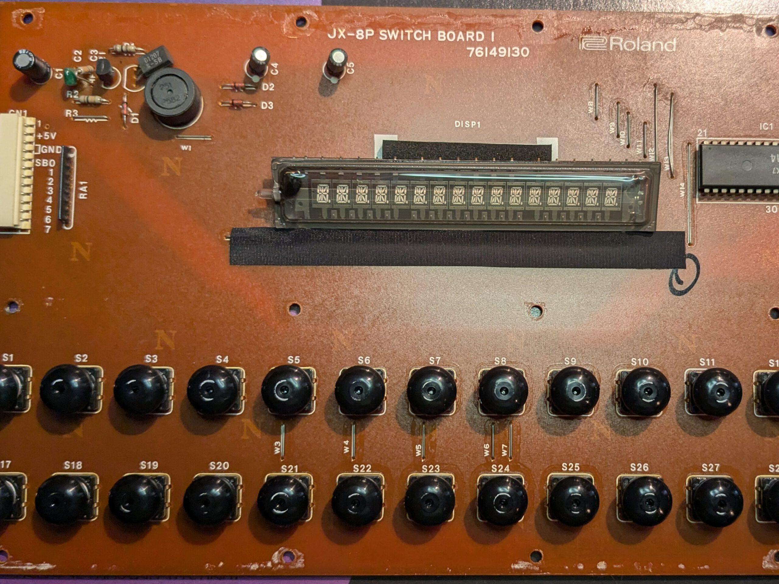
The most likely cause of a dead display is the coil driver that supplies power to the VFD. It consists of several fine windings, and over time, one of them can break. I desoldered the coil driver to check it for continuity. During the process, pin 9 literally fell off. I didn’t even touch the thing! . Great… Now I had no choice but to replace it. Or did I?
According to the coil driver’s pinout, pin 9 isn’t connected to anything. In the JX-8P schematic it’s also not connected to anything.
To properly test everything, I measured the other pins for continuity. Pins 1 and 2 were completely open, while the others checked out. So it was definitely faulty after all. Which meant I still needed a replacement.
I started looking for a replacement and found a seller on eBay asking €70 including shipping for a NOS part. That felt steep, so I kept looking. It turns out Sumida had done a new production run of these coil drivers some years ago. (Sumida LC-15) Sadly, those were also sold out everywhere, except in Russia. Several Russian websites listed hundreds of them in stock for just €0.20 each, but none of them shipped internationally. So that option was out. I briefly looked into winding one myself, but in the end, I went with the eBay seller. I had gotten the JX-8P for a good price, and having a working display would make it much more valuable.
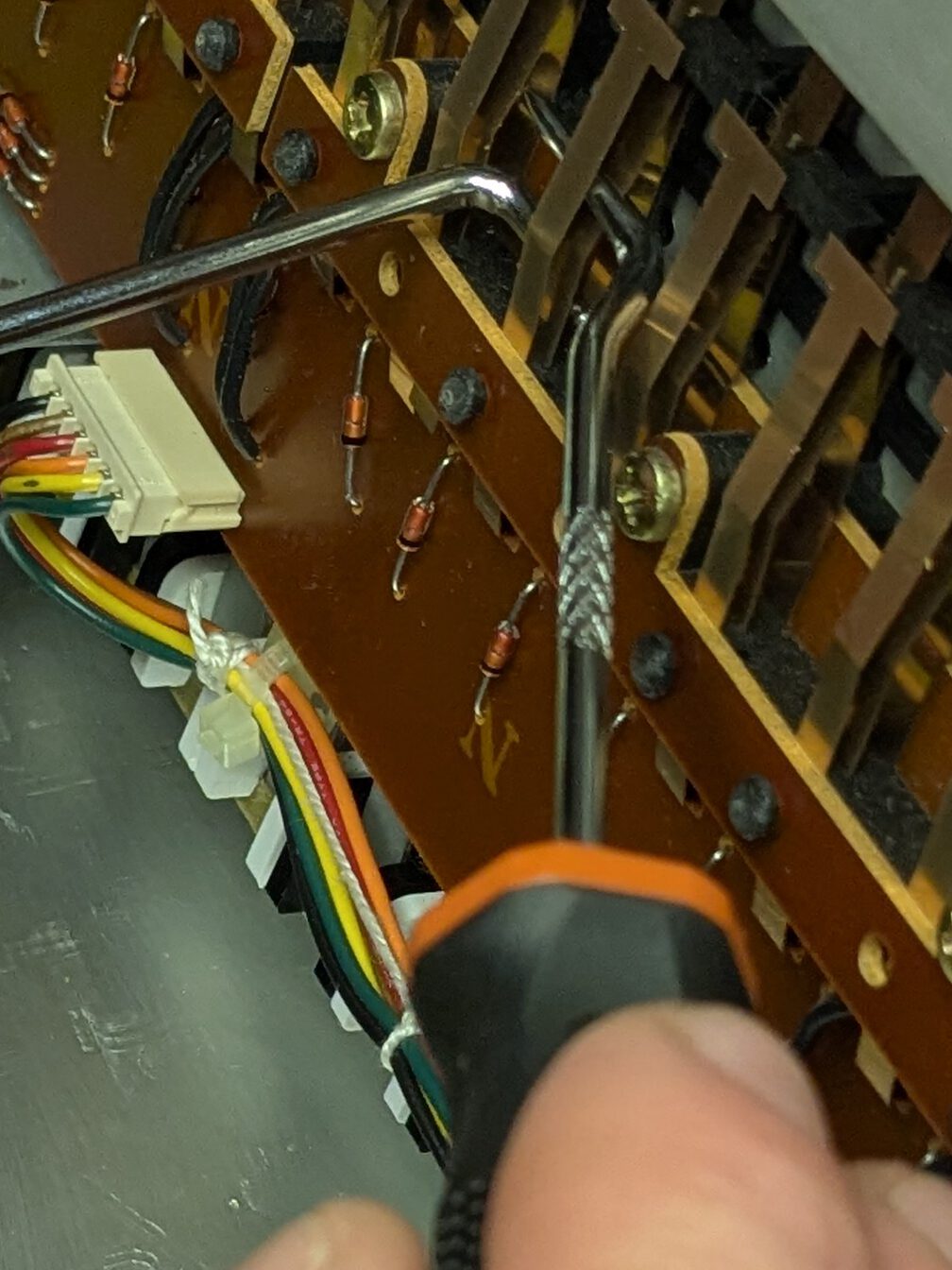
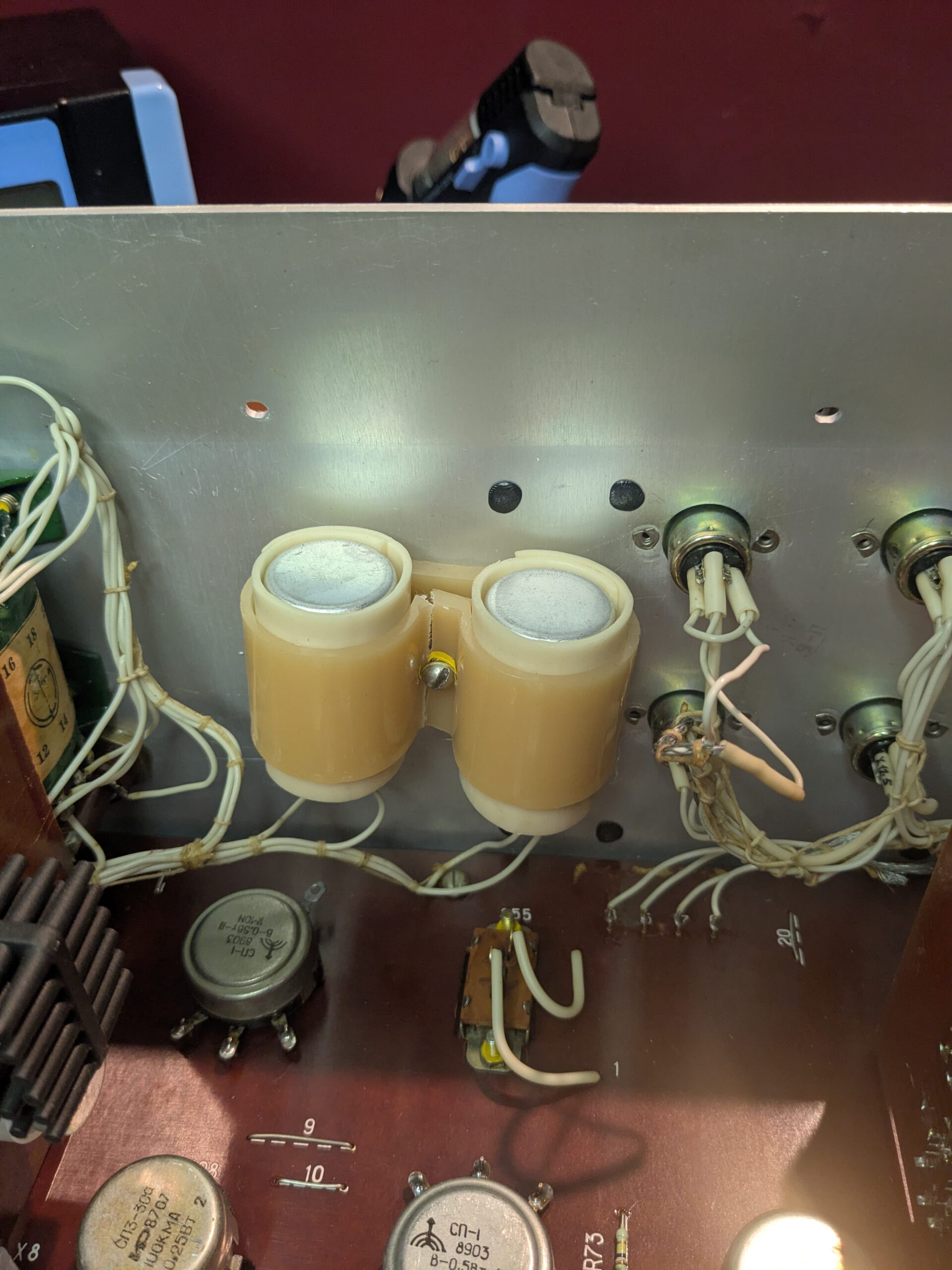
The replacement arrived quickly. I tested it for continuity before installing and it checked out fine. The coil driver sits on Switch Board 1, which is hidden under the mainboard. I had to remove the mainboard to get to it.
While reinstalling the display, which is mounted to the case, I noticed the VFD window on the housing was dirty, so I cleaned it with a bit of isopropyl alcohol. That was a big mistake. The display has a black-coated plastic cover with a clear viewing window in the middle. The IPA dissolved the black coating, and my neat rectangular window turned into a blotchy mess. Ouch..
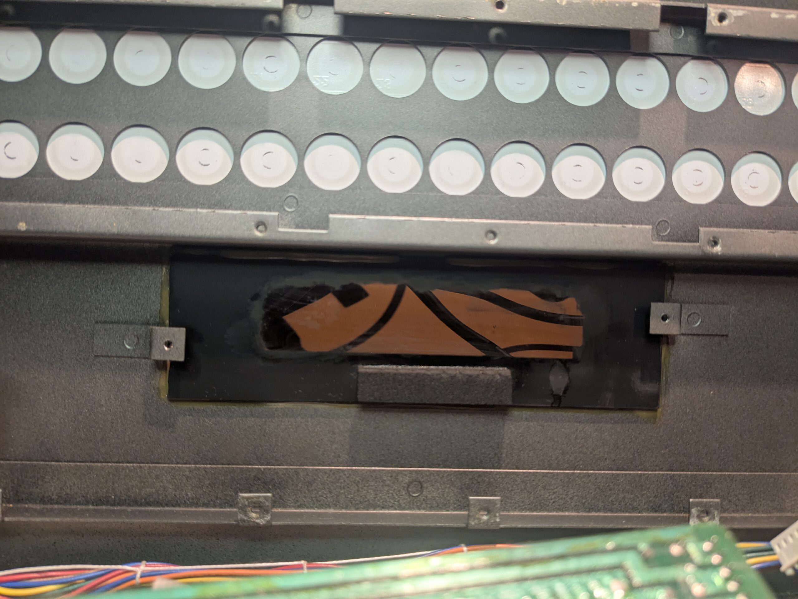
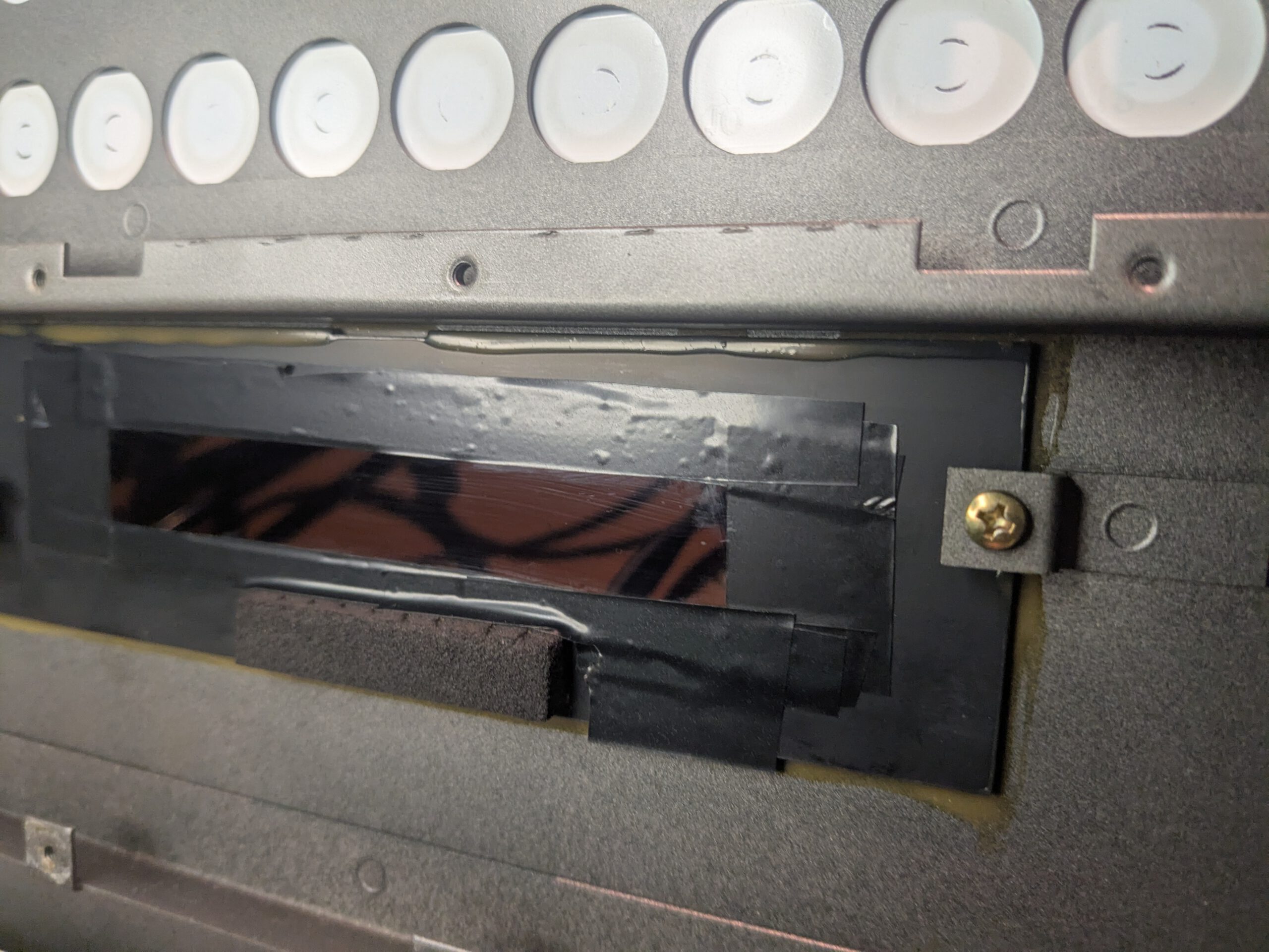
After some more research, I fixed it by applying black electrical tape to recreate a clean frame that blocks out the excess light. It doesn’t look as nice as the original coating from the inside, but from the outside, you really can’t tell the difference.
I reassembled everything, making sure to take good photos of all connectors and cables along the way. Finally, the moment of truth. Would the display work?
I powered it on, and right away, text appeared on the screen. It worked! Another issue solved! That €70 part was worth every cent.
4. Replacing some keys
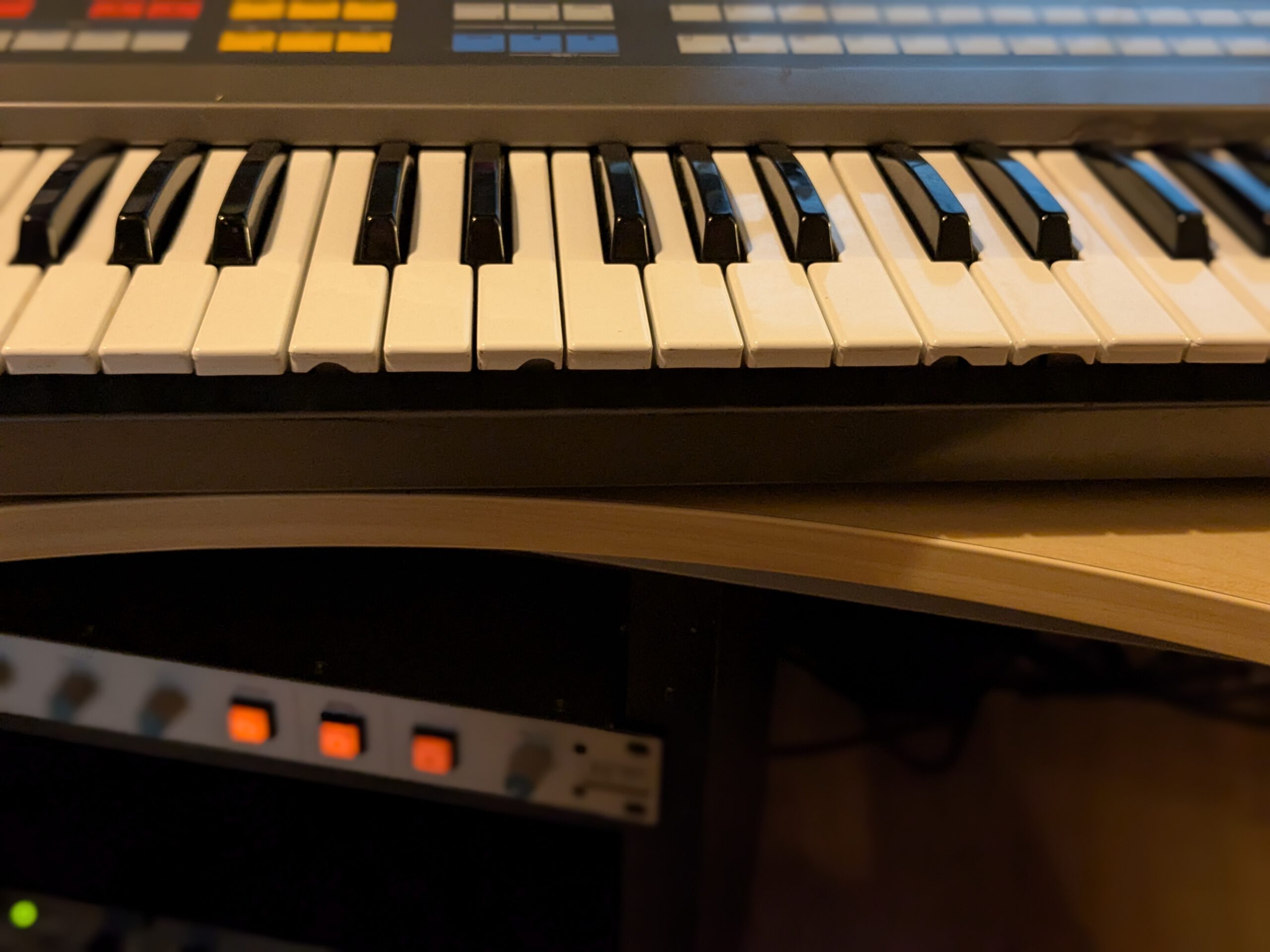
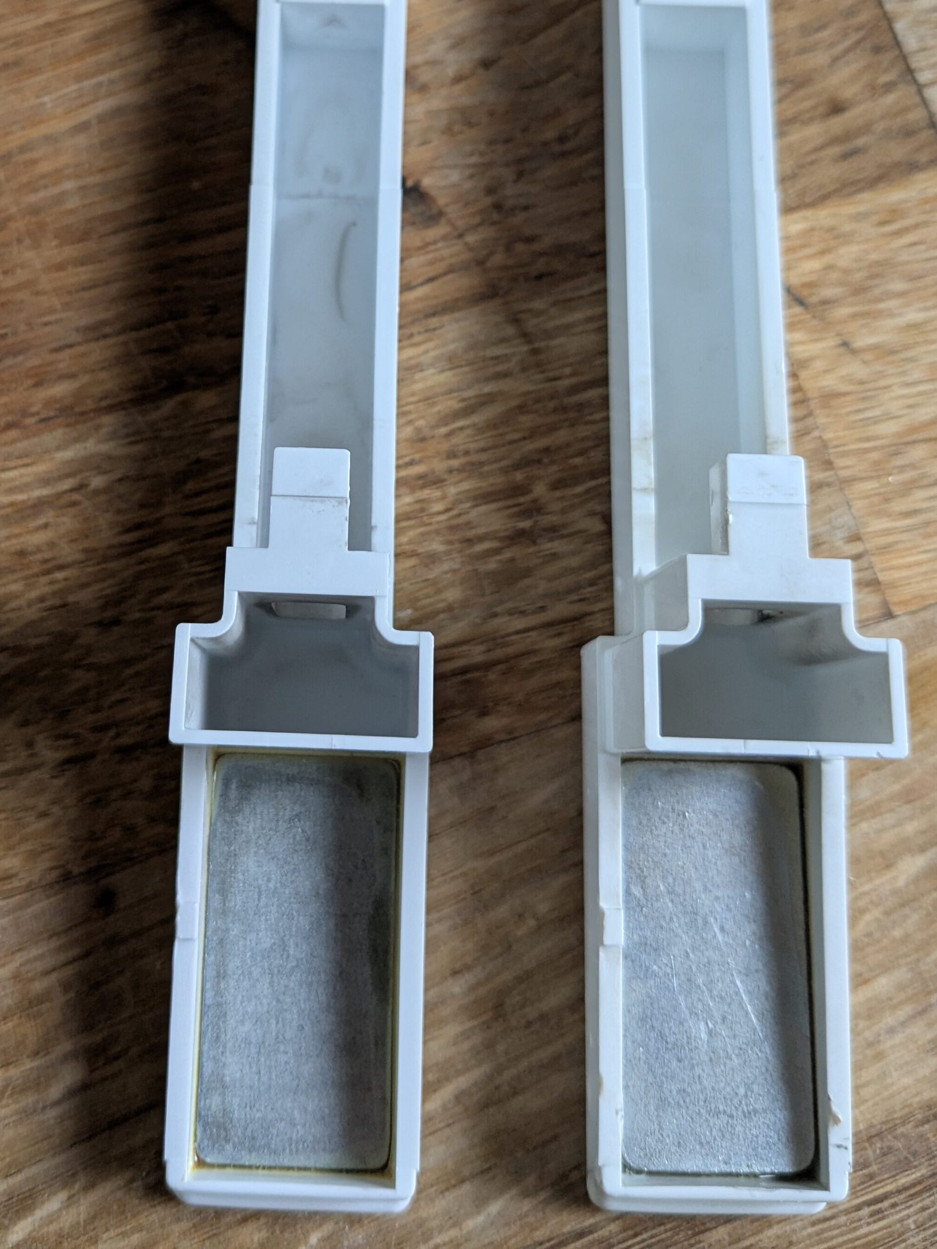
The only thing left to do was replace five keys. It looked like a mouse had gnawed on them, and when you looked at them from underneath, you could clearly see the damage. This seemed like a nice simple job to finish with.
I had a quick look around and soon found a seller offering keys suitable for the JX-8P. Keep in mind that the JX-8P has small weights under its keys. There are keys from other Roland synths that also fit, but they don’t have weights underneath. So be sure to ask about that when you order them.
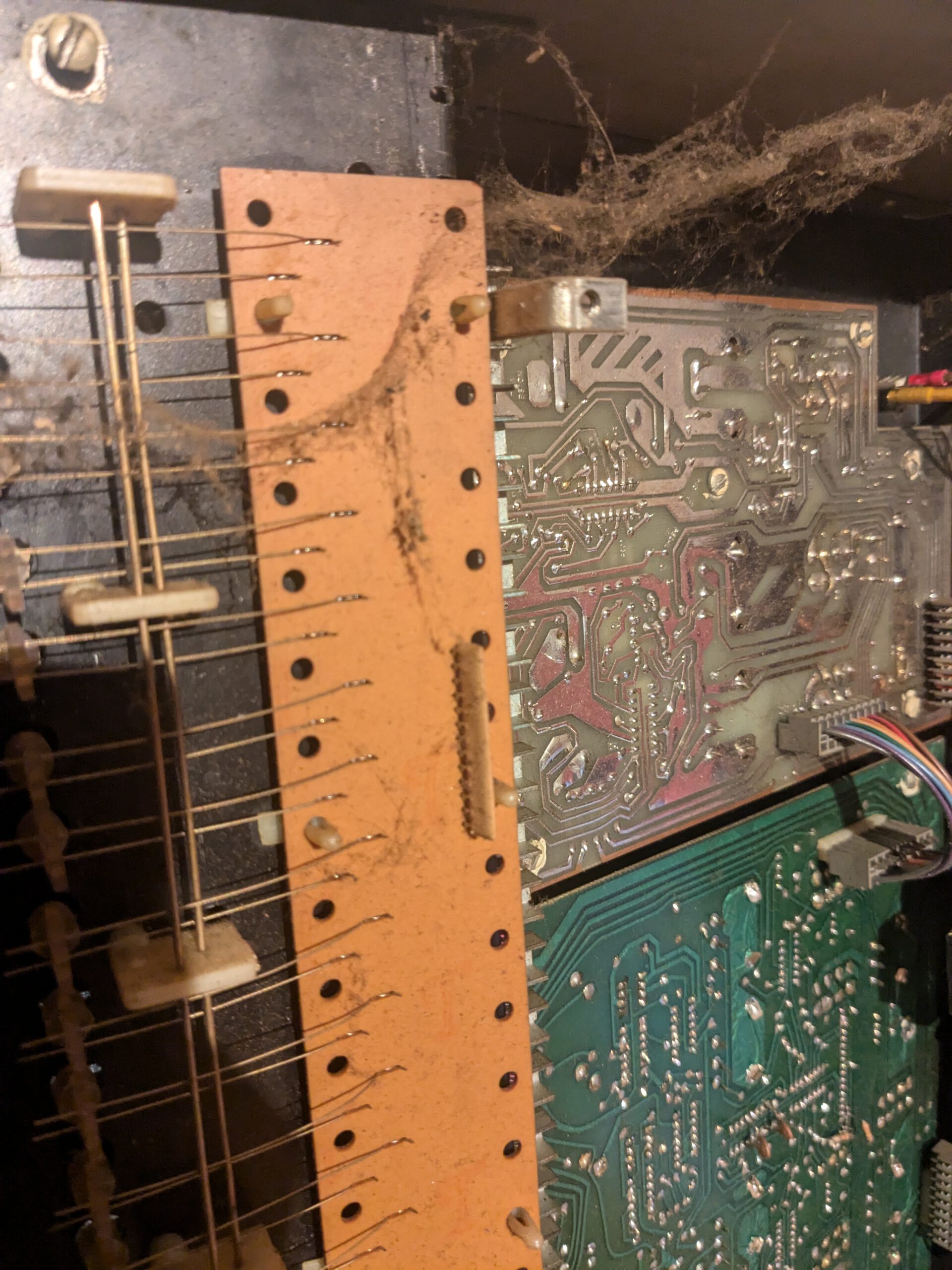
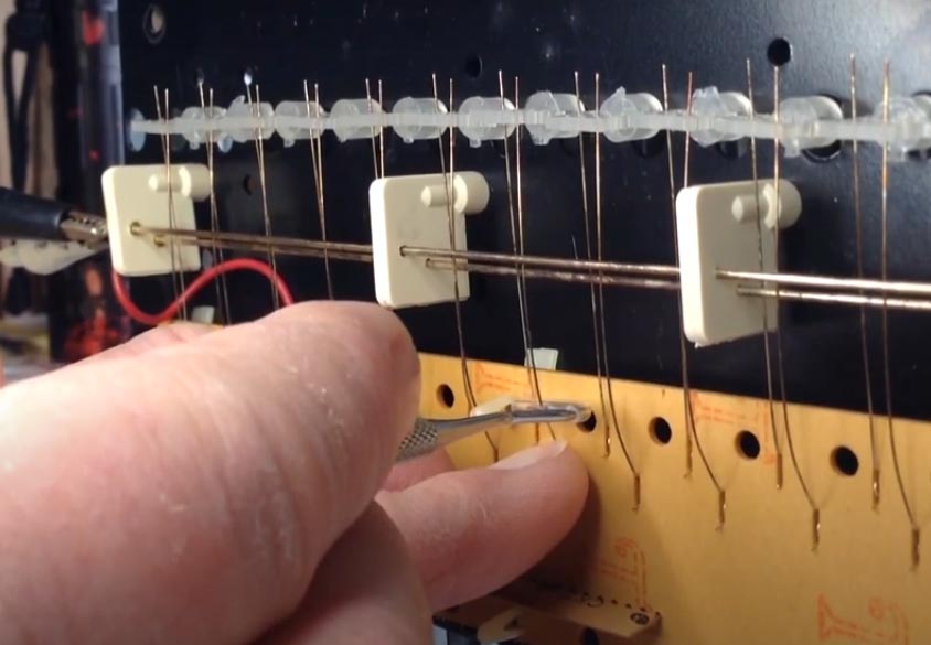
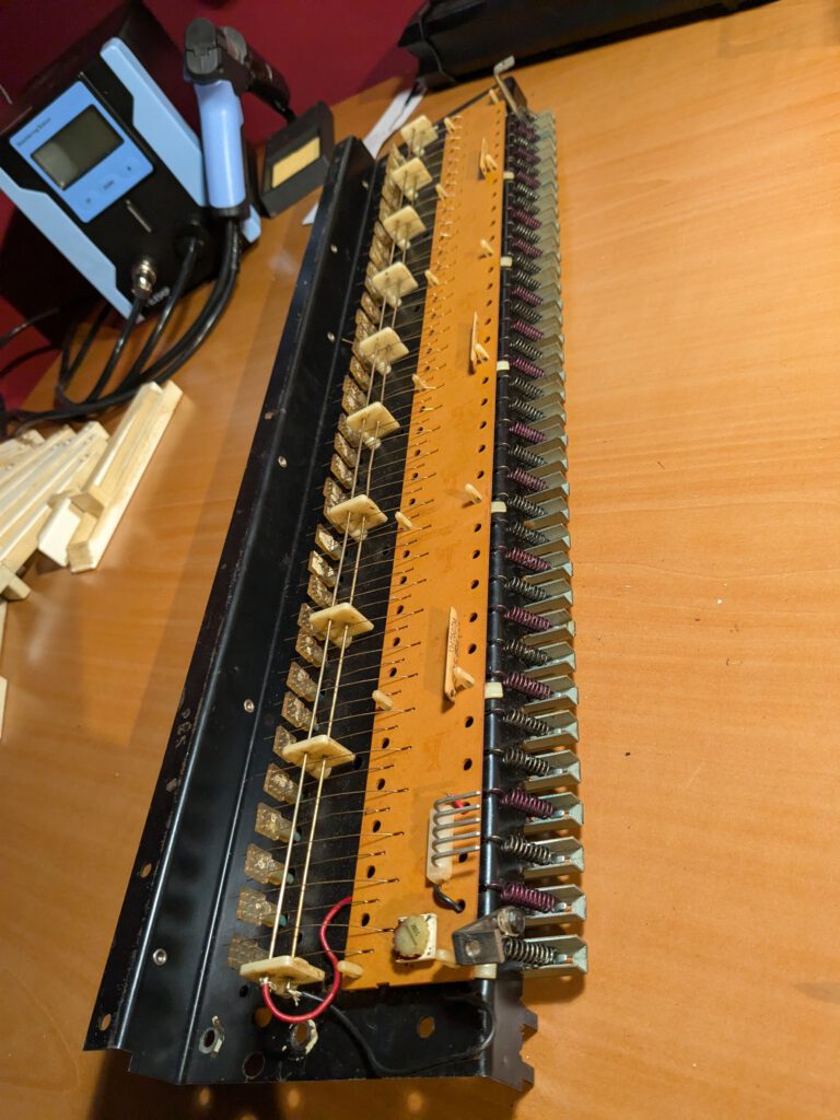
To get the keybed out, you first need to remove the side panels (6 screws) and the left side section, which can be detached from underneath with two screws. On the underside, you also need to undo four screws that belong to the keybed. Once inside the JX-8P, you will see three more screws securing the keybed; these can be removed as well. I also disconnected the connectors (three on the main board and one to the left of the aftertouch). This gives you more freedom to work on the keybed.
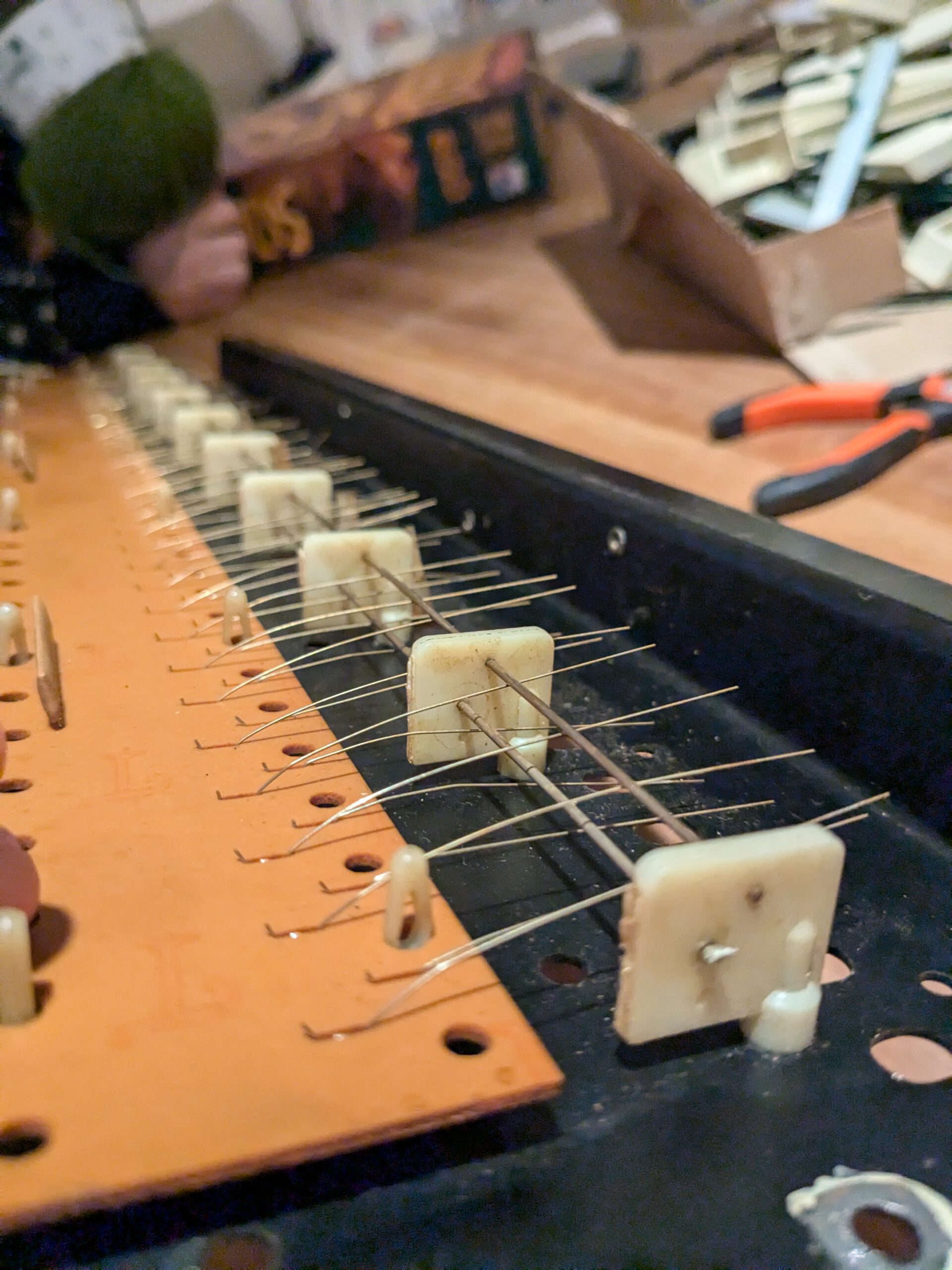
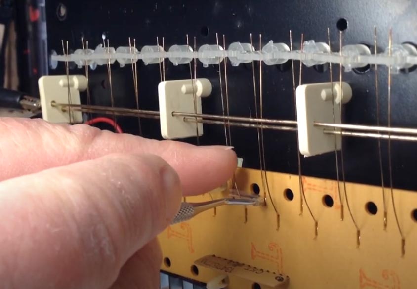
To remove the keys, you first need to take off a transparent plastic strip on the underside that holds them in place. This can be removed fairly easily. Then, the springs need to be detached. Since I wanted to clean the keybed, I removed all the springs from the keys. Note that the black keys have different springs than the white keys. After that, you can slide the keys out easily.
All keys got a wash, and I cleaned all the contacts with IPA before reinstalling the keys. When I got to number 10, I noticed some did not move smoothly. It later turned out I was pressing the key against a contact, which made it sit differently and prevented proper contact. The result was a key that produced no sound. I had five that stopped working. So be careful and make sure the key sits above the contact.
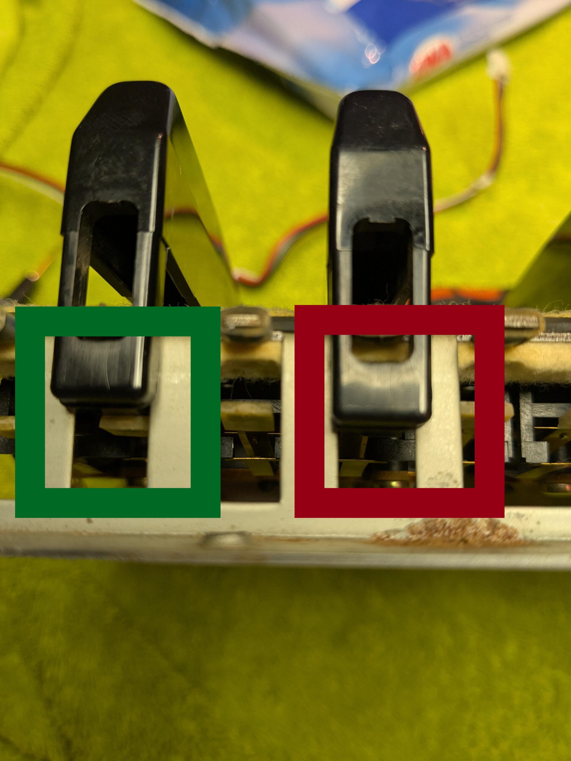
To reposition the contacts correctly, I used two small hooks. Initially, the contact rests on one strip. When the key is pressed, the copper strip moves to another contact. Both need to be able to make contact. On the keys I had mounted incorrectly, the copper strip was not touching the strip it should initially rest on. By using two hooks to slightly bend the middle strip, I was able to get it back into its original position on the contact.
So if you have keys dropping out, which I understand can occasionally happen with the JX-8P, it may well be that the strips are not making proper contact. I also noticed that they can get dirty or that dust can get between them, which could also cause this issue. Note to self: do not use cotton swabs to clean these sensitive contacts, as fibers can come off and cause more problems.
Anyway, everything looks fine again now.
5. Conclusion
This project actually went quite smoothly. If I had known beforehand that the VFD coil driver was almost impossible to find, I might have made a different choice. I was probably lucky that a NOS one was being offered for sale on eBay. Nevertheless, it can be solved if you have the right component and are willing to wait until one is offered for sale.
It did not go entirely flawlessly, considering the forgotten mica insulator tabs, the blunder with the display, and accidentally bending the contacts on a few keys, but all of that was nicely resolved as well.
Job done!


